 |
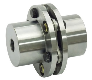
| A Single 6-Bolt Disc Pack SU Type Disc Coupling |
 |
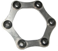
| Unitized Disc Pack Profile |
Furthermore (yes.. there are a lot of positives with this coupling type), generally being all metal (with no seals or gaskets) gives disc couplings the ability to withstand harsh environments.. And, lastly, to give one more potential major benefit (based on the application) over their lubricated brethren, disc couplings have torsional rigidity with no backlash.
Limitations of disc couplings include no vibration dampening capability (a strength of elastomeric & grid couplings), and limited misalignment handling capability... particularly in regards to parrallel misalignment. (For a disc coupling to handle parallel misalignment, two disc packs must be used.) Additional considerations include speed limitations if not balanced (though these can be overcome as evidence by widespread disc coupling usage in API 610 and API 671 applications), and possible anti-flail concerns (though, again, anti-flail safety features can be added to many designs).
Design Basics - Disc Packs
 |
| Six Bolt Unitized Disc Pack |
The trade-off between the number of bolts is torque versus misalignment handling capability. More bolts (and more legs sharing the load) can carry higher torque loads, but this increase also decreases the flexibility of the disc pack and ability of the pack to handle increased misalignment.
 |
| Eight Bolt Unitized Disc Pack |
Disc packs are generally made of thin layers of stainless steel (though materials can vary) that have been "unitized" into a single easy to handle/install/replace unit by use of bushings. Some early and current designs styles still make use of non-unitized layers, which can be a bit trickier to deal with from a maintenance and handling perspective. (Note: All of Lovejoy's disc couplings leverage a unitized design.)
As illustrated in the diagram of the 6 bolt disc pack below, fasteners are then used to connect the disc pack bushings to the coupling flanges. For each bushing location, the disc pack will be connected to only one of the two coupling flanges and the flange it is connected to will switch back and forth as you circle around the disc pack in either direction.
 |
| Disc Pack Bushings Fasten to Alternating Flanges |
To learn more about disc couplings, please go to Part 2 of this blog series... or check out Lovejoy's disc coupling product pages & catalogs, the non-lubricated section of The Coupling Handbook, and/or subscribe to this blog as there will be several more blog posts on disc couplings in the immediate future.

No comments:
Post a Comment